- 您现在的位置:买卖IC网 > Sheet目录2009 > MAX152EPP+ (Maxim Integrated Products)IC ADC 8BIT 1UA PWR-DWN 20-DIP
____________Analog Considerations
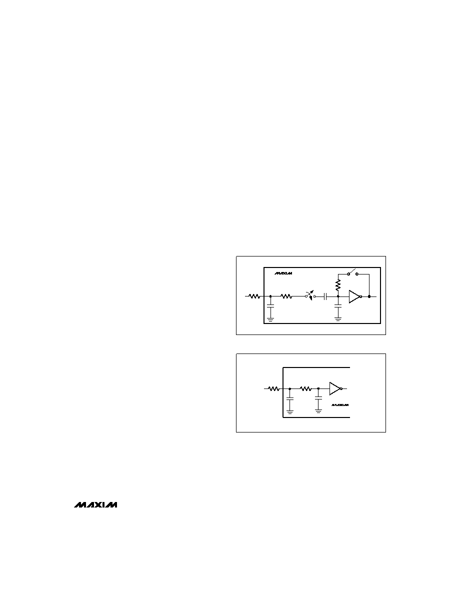
Reference
Figures 7a-7c show some reference connections.
VREF+ and VREF- inputs set the full-scale and zero-
input voltages of the ADC. The voltage at VREF-
defines the input that produces an output code of all
zeros, and the voltage at VREF+ defines the input that
produces an output code of all ones.
The internal resistance from VREF+ to VREF- may be as
low as 1k
, and current will flow through it even when
the MAX152 is shut down. Figure 7d shows how an N-
channel MOSFET may be connected to VREF- to break
this path during power-down. The FET should have an
on resistance < 2
with a 3V gate drive.
Although VREF+ is frequently connected to VDD, this
circuit uses a low current, low-dropout, 2.5V voltage
reference – the MAX872. Since the MAX872 cannot
continuously furnish enough current for the reference
resistance, this circuit is intended for applications where
the MAX152 is normally in standby and is turned on in
order to make measurements at intervals greater than
20s. The capacitor C1 connected to VREF+ is slowly
charged by the MAX872 during the standby period and
furnishes the reference current during the short measure-
ment period.
The 2.2F value of C1 is chosen so that its voltage drops
by less than 1/2LSB during the conversion process.
Larger capacitors reduce the error still further. Use
ceramic or tantalum capacitors for C1.
When VREF- is switched, as in Figure 7d, a new conver-
sion can be initiated after waiting a time equal to the
power-up delay (tUP) plus the turn-on time of the N-chan-
nel FET.
Bypassing
A 4.7F electrolytic in parallel with a 0.1F ceramic
capacitor should be used to bypass VDD to GND.
These capacitors should have minimal lead length.
The reference inputs should be bypassed with 0.1F
capacitors, as shown in Figures 7a-7c.
Input Current
Figure 8 shows the equivalent circuit of the converter
input. When the conversion starts and
WR is low, VIN is
connected to sixteen 0.6pF capacitors. During this acqui-
sition phase, the input capacitors charge to the input volt-
age through the resistance of the internal analog switches.
In addition, about 12pF of stray capacitance must be
charged. The input can be modeled as an equivalent RC
network (Figure 9). As source impedance increases, the
capacitors take longer to charge.
The typical 22pF input capacitance allows source resis-
tance as high as 2.2k
without setup problems. For larg-
er resistances, the acquisition time (tP) must be increased.
MAX152
+3V, 8-Bit ADC with 1A Power-Down
_______________________________________________________________________________________
9
RON
RIN
VIN
1
C
VIN
MAX152
Figure 8. Equivalent Input Circuit
4k
R
VIN
1
12pF
VIN
MAX152
10pF
Figure 9. RC Network Equivalent Input Model
发布紧急采购,3分钟左右您将得到回复。
相关PDF资料
MAX153EPP+
IC ADC 8BIT 1MSPS HI-SPD 20-DIP
MAX154AENG+
IC ADC 8BIT 4CH W/MUX&REF 24-DIP
MAX155AEPI+
IC ADC 8BIT 8CH T/H&REF 28-DIP
MAX157AEUA+
IC ADC 10BIT 108KSPS 2CH 8-UMAX
MAX160CPN+
IC ADC 8BIT UP COMPATIBLE 18-DIP
MAX165ACPN+
IC ADC CMOS 8BIT UP COMP 18-DIP
MAX170CEPA+
IC ADC 12BIT SERIAL 8-DIP
MAX173CNG+
IC ADC 10BIT W/REF 24-DIP
相关代理商/技术参数
MAX152EVKIT-DIP
功能描述:数据转换 IC 开发工具 MAX152 Eval Kit RoHS:否 制造商:Texas Instruments 产品:Demonstration Kits 类型:ADC 工具用于评估:ADS130E08 接口类型:SPI 工作电源电压:- 6 V to + 6 V
MAX152EWP
功能描述:模数转换器 - ADC Integrated Circuits (ICs) RoHS:否 制造商:Texas Instruments 通道数量:2 结构:Sigma-Delta 转换速率:125 SPs to 8 KSPs 分辨率:24 bit 输入类型:Differential 信噪比:107 dB 接口类型:SPI 工作电源电压:1.7 V to 3.6 V, 2.7 V to 5.25 V 最大工作温度:+ 85 C 安装风格:SMD/SMT 封装 / 箱体:VQFN-32
MAX152EWP+
功能描述:模数转换器 - ADC 8-Bit 400ksps 3V Precision ADC RoHS:否 制造商:Texas Instruments 通道数量:2 结构:Sigma-Delta 转换速率:125 SPs to 8 KSPs 分辨率:24 bit 输入类型:Differential 信噪比:107 dB 接口类型:SPI 工作电源电压:1.7 V to 3.6 V, 2.7 V to 5.25 V 最大工作温度:+ 85 C 安装风格:SMD/SMT 封装 / 箱体:VQFN-32
MAX152EWP+T
功能描述:模数转换器 - ADC 8-Bit 400ksps 3V Precision ADC RoHS:否 制造商:Texas Instruments 通道数量:2 结构:Sigma-Delta 转换速率:125 SPs to 8 KSPs 分辨率:24 bit 输入类型:Differential 信噪比:107 dB 接口类型:SPI 工作电源电压:1.7 V to 3.6 V, 2.7 V to 5.25 V 最大工作温度:+ 85 C 安装风格:SMD/SMT 封装 / 箱体:VQFN-32
MAX152EWP-T
功能描述:模数转换器 - ADC RoHS:否 制造商:Texas Instruments 通道数量:2 结构:Sigma-Delta 转换速率:125 SPs to 8 KSPs 分辨率:24 bit 输入类型:Differential 信噪比:107 dB 接口类型:SPI 工作电源电压:1.7 V to 3.6 V, 2.7 V to 5.25 V 最大工作温度:+ 85 C 安装风格:SMD/SMT 封装 / 箱体:VQFN-32
MAX152MJP
功能描述:模数转换器 - ADC RoHS:否 制造商:Texas Instruments 通道数量:2 结构:Sigma-Delta 转换速率:125 SPs to 8 KSPs 分辨率:24 bit 输入类型:Differential 信噪比:107 dB 接口类型:SPI 工作电源电压:1.7 V to 3.6 V, 2.7 V to 5.25 V 最大工作温度:+ 85 C 安装风格:SMD/SMT 封装 / 箱体:VQFN-32
MAX15300ETI+
功能描述:DC/DC转换器 Auto-Comp digital PoL controller RoHS:否 制造商:Murata 产品: 输出功率: 输入电压范围:3.6 V to 5.5 V 输入电压(标称): 输出端数量:1 输出电压(通道 1):3.3 V 输出电流(通道 1):600 mA 输出电压(通道 2): 输出电流(通道 2): 安装风格:SMD/SMT 封装 / 箱体尺寸:
MAX15300ETI+T
功能描述:DC/DC转换器 Auto-Comp digital PoL controller RoHS:否 制造商:Murata 产品: 输出功率: 输入电压范围:3.6 V to 5.5 V 输入电压(标称): 输出端数量:1 输出电压(通道 1):3.3 V 输出电流(通道 1):600 mA 输出电压(通道 2): 输出电流(通道 2): 安装风格:SMD/SMT 封装 / 箱体尺寸: